Looking for collaboration for your next project? Do not hesitate to contact us to say hello.
CEPT
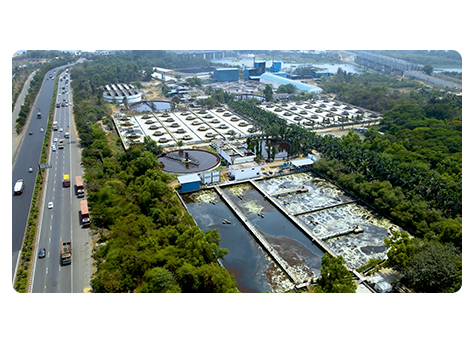
Common Effluent Treatment Plant
Vapi CETP is a conventional plant consisting of physical, chemical, biological treatment. An outline of plant design is given in figure. The plant receives combined wastewater, consisting of both domestic and industrial waste from the various industries in the area.
The waste water generated by all industrial units is conveyed to CETP through an underground pipeline network.


Primary Treatment
Primary Treatment
The main incoming chamber receives the influent from where it goes to coarse screen chamber for removal of large floating particles, plastics. After the coarse screen the effluent then moves to automatic fine Screen chamber.
Automatic Fine Screen
The fine screening is done by automatic screening system. The fine screens are capable of handling solids up to size of 4mm. The scrum gets collected automatically in the waste bins.
Grit Chamber
The next stage of treatment is done in de-gritter units where the sand grit particles are removed through grit classifier. The purpose of grit removal is to remove the heavy inorganic solids which cause excessive mechanical wear. Grit is heavier than organic solids and includes, sand, gravel, clay, metal filings, seeds, and other similar materials.
Equalization Tank
The equalization tanks are there to equalize the temperature, quality and flow rate of the water. Equalization is a process to equalize wastes by holding waste streams in a tank for a certain period of time prior to treatment in order to obtain a stable waste stream that is easier to treat. Equalization helps in mixing smaller volumes of concentrated wastes with larger volumes at lower concentrations. It also controls the pH to prevent fluctuations that could upset the efficiency of treatment system, by mixing acid and alkaline wastes. Equalization tanks are equipped with coarse diffused system that helps not only in proper mixing of waste water but also prevents suspended solids from settling to the bottom of the unit.
Flash Mix & Flocculator
The effluent is then pumped into flash mixer and flocculator tanks where dosing of Aluminum chloride and polyelectrolyte is done respectively so to coagulate and flocculate the solids before going into primary clarifier.
Primary Clarifier
The overflow from flash mixer and flocculator then by gravity flows into primary clarifier where the settling takes place. The sludge is scrapped from the bottom into sludge collection tank and is then pumps to sludge thickeners. The overflow from primary clarifier flow into aeration tanks and part of the waste water is being fed to UASBs. A typical sedimentation tanks may remove from 70 to 80 percent of suspended solids, and from 15 to 25 percent of biochemical oxygen demand (BOD) from the waste water.
Secondary Treatment
Aeration Tank
Aeration tank consist of surface aerators. Here biological treatment take place and maximum reduction in terms of COD and BOD take places. Return Activated Sludge (RAS) is circulated in the system in order to maintain desired level of MLSS. Aerobic oxidation of organic matter is carried out in this tank.
Primary effluent is introduced and mixed with Return Activated sludge (RAS) to form the mixed liquor, which contains 4500–5500 mg/L of suspended solids.
An important characteristic of the activated sludge process is the recycling of a large portion of the biomass. This makes the mean cell residence time (i.e., sludge age) much greater than the hydraulic retention time This practice helps maintain a large number of microorganisms that effectively oxidize organic compounds in a relatively short time.
Oxygen supplied by the surface aerators is consumed by the micro organism to convert complex hydrocarbons (Organic Pollutant) to simple hydrocarbons like CO2 and H20.
UASB Reactors (Up Flow Anaerobic Sludge Blanket)
Overflow from primary clarifier, concentrated waste water from dewatering units and partial condensate from CMEE are taken in to UASB reactor for anaerobic digestion the flow is pumped in to the reactor in upward flow and over flow from the top is been taken back in to the equalization tank for further aerobic treatment. As it is an anaerobic digestion methane gas is obtain from the reactor and is currently flared but shall be used as resource for generating power in future. The UASB reactor is a methanogenic (Methane producing).UASB uses an anaerobic process whilst forming a blanket of granular sludge which suspended in the tank. Waste water flows upward through the blanket and is processed (degraded) by anaerobic microorganisms. The upward flow combine with settling action of gravity suspends the blanket with aid of flocculants.
Secondary Clarifier
From aeration tank the effluent, partially by gravity and partially by pumping taken in to secondary clarifier. Dosing of aluminum chloride is done in the clarifier and the sludge is scrapped form the bottom and the overflow go to final outlet.
Sludge Handling
Sludge from primary clarifiers and Waste Activated sludge from RAS pumping is collected into sumps from where it is pumped to thickeners. The thickened sludge is then pumped to decanters. The solid cake is bagged in to used HDPE bags and stored at SDBs and Interim sludge storages for removal of leachate and sun drying. The bagged sludge is being sent for land filling at TSDF –Vapi. Overflow of the thickeners and leachate from decanter goes to filtrate tank which is again brought back into system. Sludge from UASB & RAC is also dewatered through Decanters.
SDB/Interim Storages
The bagged sludge from decanter house is being stored in SDBs and Interim storages for removal of leachate and sun drying. The leachate generated is taken back to the system for treatment.